The SmartWi Toolbox has a number of functions to analyse and resolve possible issues with your SmartWi. The general function is described below. If you did not download and install the Toolbox, you may find it here.
Please note that there is only one Toolbox that works with all SmartWi versions.
Before trying to download and install new firmware with the Toolbox, it may be helpful to check the Master and the client cards to see whether everything is already functioning as it should.
Some frequently asked questions:
1. How can I check the firmware version?
2. How can I update the firmware?
3. How can I change the channel / wireless transmission frequency?
4. How can I check the function of the client cards?
5. How can I monitor the communication between Master and client cards?
6. How can I create a log file?
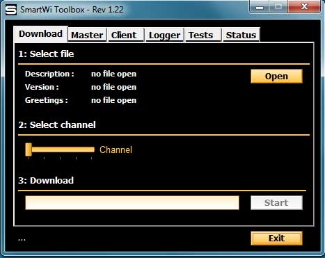
Fig 1: The initial image when the Toolbox is opened. The Download TAB is used when you want to update the SmartWi Firmware version and/or change the channel.
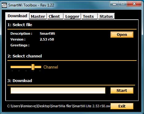
Fig. 2: The image shows the Toolbox ready to update the firmware version. After downloading the firmware from smartwi.net, save it to a known location.
1. Push the Open button and navigate to the downloaded firmware.
2. Mark the file, and the Start button turns yellow.
3. The Toolbox is ready to overwrite the current version of firmware. Note that there is a Channel selector which is normally to the left. This means that the new firmware will be installed with the standard frequency of 868,0 MHz. If you want/prefer a different frequency, pull the Channel bar to the right with the cursor. Each step increases the frequency by 0,2 MHz. This option may be used if you suspect that the used channel is disrupted in some way such as other electronic devices in your home. This may be new ‘smart home’ controls, monitoring of electric and water systems or security alarms that may use the same or very close frequencies to the SmartWi channels.
Important note: If you changed the channel, remember to pair the Master and the client cards again. The new frequency will be copied to the client cards.
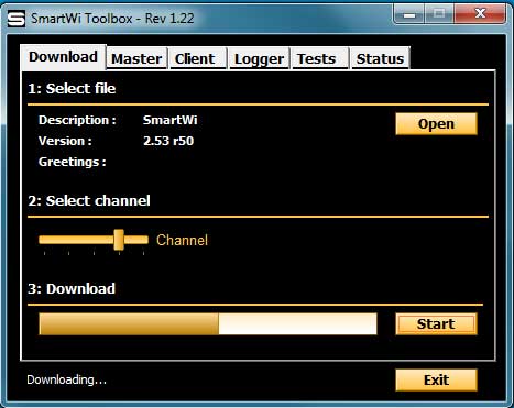
Fig. 3: The image shows the progress when updating the SmartWi Firmware version. The 2.53 r50 is the standard firmware installed in all new SmartWi Masters. Note the progress bar under Download at the bottom. The process normally takes 4-6 seconds, and the new firmware is ready when the bar reaches the far right side.
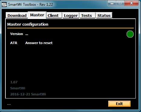
Fig. 4: The image shows the opening window under the Master TAB. This is mainly used to display the Master configuration. This is recommended before trying to install a new firmware version. The opening image does not show the version – please see next image. The image mainly shows the time of the first programming – from the factory – and possibly the name of the distributor.
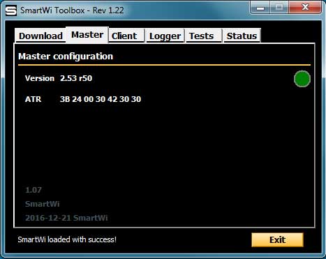
Fig. 5: The image shows the data from the Master. Important note: Insert a card – any card – in the card reader.
1. The firmware version in this Master is the newest version. Most often this means that there is no reason to update the firmware, but in some cases SmartWi may function better with an older version.
2. The ATR means Answer-To-Reset. This must be shown, after the Master was paired with the provider smart card. The ATR is essential for the communication with the client cards, and the number must be identical with the numbers from the Clients – see below. Note: The numbers are unique for each broadcaster, and may be much longer than the 16 digits shown here.
Fig. 6: This is the opening image when pressing the Client TAB. For the functions of this TAB, please see below.
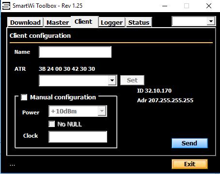
Fig. 7. Insert the Client in the Master card reader. The image shows the data from a Client card after it has been paired with the Master.
1. The ATR number was automatically transferred during the initial pairing. Note that it is identical with the number from the Master. If the numbers are not identical, or if there is no number displayed, the card is not correctly paired or it is defect.
2. It is possible to change some of the settings in the Client, using the Manual configuration, including the transmission strength, but this is usually not necessary with newer receivers. Not recommended for anyone without technical insight.
3. If you want to monitor the communication progress – see Status below – you may give the Client a name – for instance the room where the card is used. Simply write the name and press Send. This has no consequence for the technical function of the card.
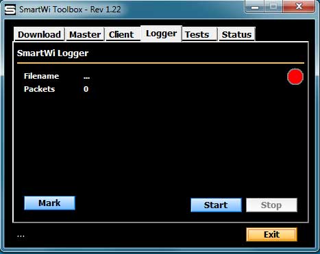
Fig. 8: The image shows the Logger option. It is possible to create a log file – a text file, that may be used for a technical analysis of the communication and the encryption data received via the signal. This is only for the use of the SmartWi engineers, and it has no practical use for anyone else.
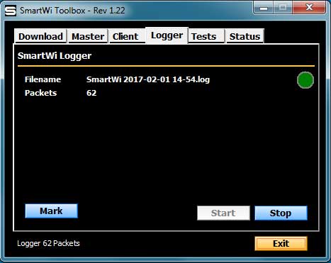
Fig 9: The image shows the progress when creating a log file. In rare cases it is necessary to analyse in-depth how the communication functions. SmartWi Support may ask a customer to create a log file, using this set-up.
1. Turn off all receivers.
2. Press the blue Start button.
3. A file is automatically created – see after Filename.
4. Turn on the first receiver. The number of ECM and EMM data packets is shown.
5. After a few minutes, turn on the next receiver. Press Mark to indicate when a change is made.
6. Repeat with the remaining receivers.
7. Press Stop. The recording is stopped, and the log file is stored in the Toolbox folder – see below. Find the file and send it to SmartWi Support.
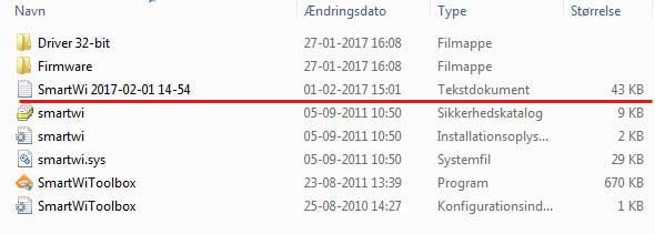
Fig. 10: The image shows the SmartWi Toolbox folder after creating a log file, with the time and date. It is a normal text file, however not readable without a special reader. Copy the file and send it to SmartWi Support.
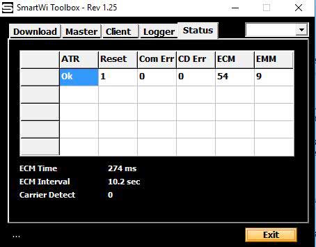
Fig. 11: The image shows the progress when the SmartWi is working – when creating a log file or just normal operation. This may be very useful in trying to identify possible problems with the SmartWi such as temporary disturbances. The image shows the ideal function with one receiver turned on. Please follow this procedure:
1. Turn off all receivers.
2. Initiate the Toolbox, and press Status.
3. Turn on a receiver. ATR: Within seconds, line 1 will display a range of information. In this case it shows that the ATR numbers are correct. This may or not be shown for all receivers.
Reset: The Reset is an initiation command sent from the Client to the Master, when the receiver is turned on. It may not be shown for all receivers.
Com Err: The Com Err is short for communication error, and this is of high interest. In this case the 0 is perfect, but there may come a few errors without major consequence. If the errors run in the hundreds, and keep coming for some time, it may cause temporary lack of service to the receiver.
CD Err:Means Carrier Detect Error. When a tv is turned on, the Client card will initially check if another carrier/client is sending. This may also be electronic noise from the tv / receiver that the card is inserted in. In this case the Client does not ‘dare’ to send. The problem is normally solved by changing the channel.
ECM: The ECM shows the number of ECM data packets received. ECM is part of the encryption data, and the packets normally come with intervals around 10 seconds. In this case the precise interval is 10.2 seconds – see below.
EMM: Also a part of the encryption data – normally with bigger intervals than the ECM packets.
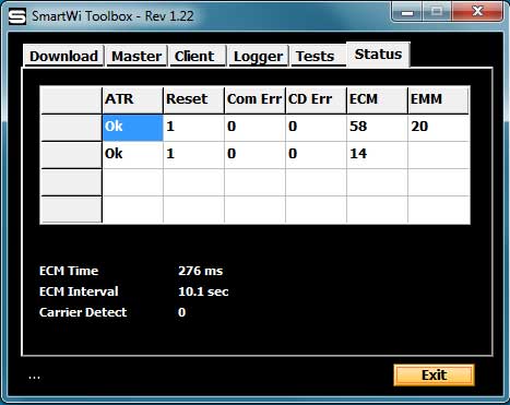
Fig. 12. The image shows the same as under the previous. When the first receiver has been monitoring for some minutes, turn on the next receiver. The progress will be shown similar to the previous. Note: If the client cards were named as described earlier, the names will appear in this display. Otherwise the receivers will be shown as seen here, and somewhat more difficult to identify